Page 7 of 9
Posted: Mon Dec 19, 2005 12:04 am
by Bugle
Rodeobob wrote:Hey Bugle id weld all them holes up so you can be sure its painted both sides and in between both bits of metal.
Put captive nuts on the lower bits and bolts in the valeys of the tray. That way you can seal beween the two layers of metal and the acid or water cant get in and make more tin worm.
Good job it will look new when your done, well atleast under the hood will. lol.
bob.
I'm just going to stick bolts in each one of those holes I think. They can't interfere with the battery because I don't think the battery sits over that far. Will try to get some bolts at the other corners and several in the valleys on the tray pretty much where they had the spot welds originally.
Best thing about the removable setup is you can actually take the tray out if any spills happen so it should be good forever.
Posted: Mon Dec 19, 2005 12:25 am
by Rodeobob
I rekon you would only need 4 bolts. Two either end.
Bob.
Posted: Tue Dec 20, 2005 12:47 pm
by Bugle
I'd rather just fix it down as securely as original
It also reinforces the radiator support I welded some tabs on there to drill holes through as originally they mig welded the tray to the support.
Posted: Thu Dec 22, 2005 12:19 am
by Bugle
Going to make adaptor so I can dump roms onto the computer tomorrow hopefully.
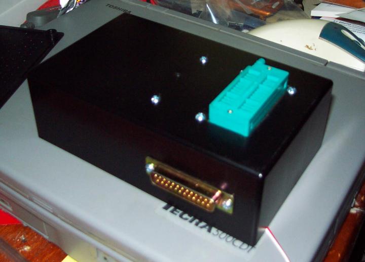
Just got an R31 Pintara CA20E ecu to compare what I find in the ROM.. The pinouts on the ECU are the same as the Piazza minus the check engine lamp output and a boost switch which the Piazza ECU uses (one of those round things in the engine bay with vacuum line going to it). Internally they look a bit different but appear to have the same ROM.
This is a pic of the 2 things. Piazza left, Pintara right. Note I have removed the ROM from the Piazza board already. So big (650KB) that I linked it instead
http://www.starlyon.com/bugle/piazza/ecu/ecus.jpg
Posted: Thu Dec 22, 2005 1:43 am
by Rodeobob
My bad. I just realized i never emailed you the pics of the I-Tec rodeo ECU's.
I hope you can handle a 8mb email. lol
Cheers. Bob.
Posted: Thu Dec 22, 2005 11:43 am
by Bugle
haha yeah got the mail
That early ECU rodeo uses a similar processor to the Piazza ECU these are some specs on it
http://www.cpu-world.com/CPUs/630x/Hita ... 303XP.html
and specs on the Piazza ecu one
http://www.cpu-world.com/CPUs/630x/Hita ... 01V1P.html
The chip in the middle of that funny blue socket is the ROM, what numbers does that have written on it? The later ecu looks to not have any external ROM bugger.
Posted: Sat Dec 24, 2005 11:56 pm
by Rodeobob
Bugle wrote:The chip in the middle of that funny blue socket is the ROM, what numbers does that have written on it?.
Cant make it out in any of the pics ive got. I will have a look in both early ECU's and let you know.
Bugle wrote:The later ecu looks to not have any external ROM bugger.
Is that meant to be..........................ROM, Bugger!!!!!!. Or is "ROM Bugger" and official title.
Bob.
Posted: Sun Dec 25, 2005 6:36 pm
by Bugle
lol no external ROM, bugger! Means that the program and fuel maps are stored inside the microcontroller which makes it harder to get them out.
The ROM on the early ECU looks like it's probably a standard 28 pin EPROM. The sticker would be covering the hole which is used for erasing the memory by shining UV light into it.
I've been working on adapting the Piazza ROM to the 28 pin rom reader and it's having trouble getting the right signals to the ROM for it to send data out. I successfully read something the Pintara ROM once don't think it's actually correct data though.
Posted: Sat Dec 31, 2005 3:15 pm
by Bugle
Been doing a bit of painting n stuff. But it's been nearly 40 degrees for the past week or so and it's hard to get motivated enough to go out and do shit in that heat.
Had no luck making an adaptor to go with that other rom reader so I decided to make my own one and write my own program to use it..
I'm just having issues configuring the parallel port to accept an input now. It seems to be outputting shit all the time which prevents the ROM from outputting data.
Posted: Sat Jan 21, 2006 4:17 pm
by Bugle
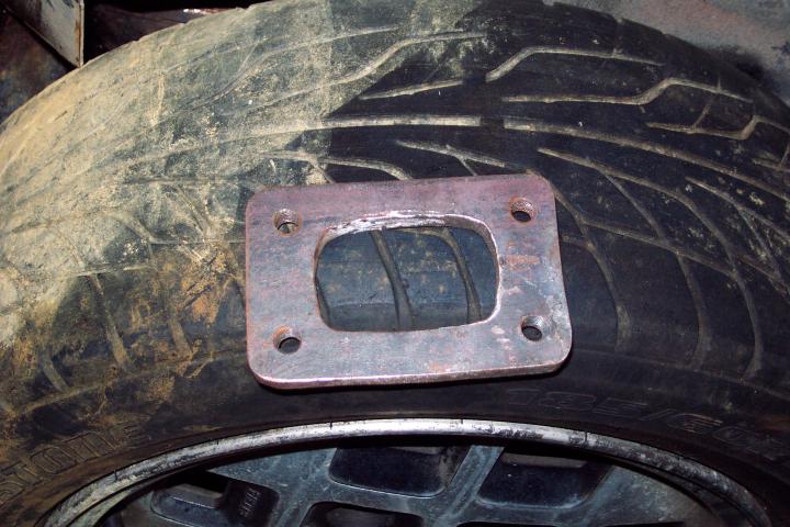
I made some flanges now I need some pipe.
Posted: Sat Jan 21, 2006 6:58 pm
by Rodeobob
Bugle wrote:I made some flanges now I need some pipe.
Did you do that yourself????
Im wanting one or two of em with 2mm bigger holes.
Bob.
Posted: Sat Jan 21, 2006 8:34 pm
by Bugle
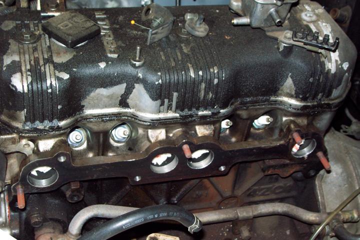
I had to make them with 35mm holes anyway because the next size hole saw down was 32mm, and the ports aren't exactly circular some spots it lines up perfect then other parts dont. If I had the head off again i'd port match the thing.
Took a while to make it though, had to oxy cut it, then finish off the edges with the angle grinder, then drill all the holes in the right places. Can you buy them from anywhere?
Posted: Sat Jan 21, 2006 10:18 pm
by Rodeobob
Bugle wrote:I had to make them with 35mm holes anyway because the next size hole saw down was 32mm, and the ports aren't exactly circular some spots it lines up perfect then other parts dont. If I had the head off again i'd port match the thing.
Took a while to make it though, had to oxy cut it, then finish off the edges with the angle grinder, then drill all the holes in the right places. Can you buy them from anywhere?
My mate was telling me he was wording up a laser cutting guy at the titty bar last week. See how that works out.
Bob.
Posted: Sun Jan 22, 2006 11:22 am
by GeminiCoupe
You can get them made up for about $100, thats for the exhaust flange and turbo flange. I forget the number to the place

but most places are around that.
Nick-
Posted: Fri Feb 10, 2006 3:12 pm
by Bugle
I finally painted the thing mostly fuck it is tedious painting an engine bay especially with the engine still in it. I think an external respray will be a breeze.
Decided to mask up the tower and do it separately as I don't want overspray off that going over the rest of the paint job.
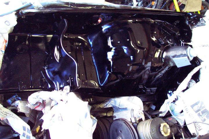
Battery tray in place not bolted in though
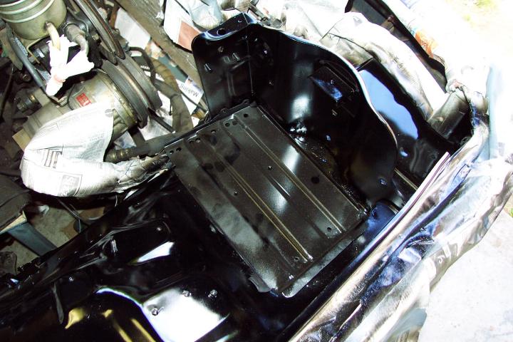
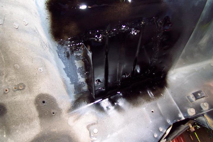
Welded some nuts on the under side to bolt the battery tray to. Also had to weld that inner guard thing mount back on as I had to remove it to fix the rust hole.