First, I am trying to sort out the heater hose setup. From what I can tell, the pipe that crosses over the back of the block feeds into the inlet of the heater core? The only two hoses I have left are the one to the valve, and the U-bend that links that pipe with a slip fitting on the pipe that goes to the coolant return pipe at the water pump. I would be happy with just a picture of those hoses and how they all connect so I could sort it out, because I have nothing to go off of.
Also, where does that pipe across the back of the block get its coolant feed from? I am assuming somewhere on the intake manifold?
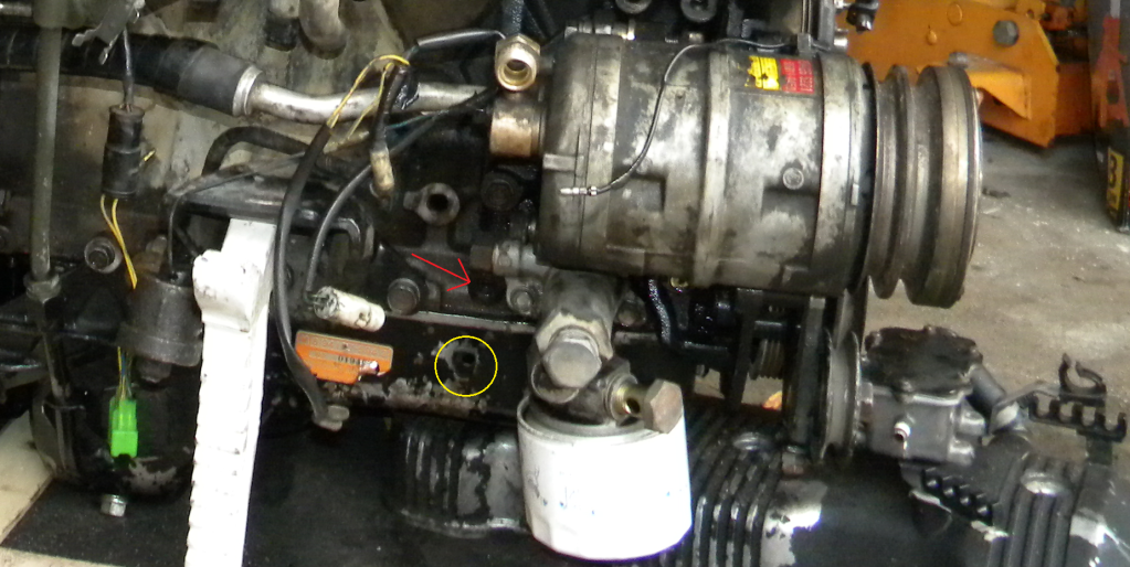
The other cooling conundrum that I have is the turbocharger coolant feed and return ports. As I don't have the stock lines I have no idea where they come from or go to. Since I am doing a 2.6 swap, I have a feeling that they aren't even present on the 2.6. Unless the smaller slip fitting on the coolant return pipe is for the turbo coolant return.... (the little port sticking up right before the 90* bend into the water pump)
I am just trying to sort out options for new feeds and returns as my new turbocharger is liquid cooled, and my PTE unit was not (so I didn't give it much thought). I am trying to keep the length of all of the lines to a minimum, but I know that it may not be entirely possible, such as the oil feed port on the 2.0 block that doesn't exist on the 2.6. I know I can utlilize and/or tap a fitting for that onto the oil filter housing or somewhere on the block.
It's all making me go cross eyed...